Science & Main


Goals

Take a stack of exhibit ideas dreamt up by the Education staff, and turn them into an exhibit in one year, on a tight budget.  The exhibit must be movable so that the exhibit hall can be used for large rental events.

Results

Science & Main is one of the most popular exhibits at the Museum, and was achieved at a fraction of the cost of most other exhibits in the museum.  See the captioned photos below for details and process photos…

Marble4
The Explora-inspired marble wall is adapted for MSC's needs: large plastic balls instead of marbles, and more durable components.
Marble 1
A photo of the marble wall shortly after opening. I added rubber edge-protectors and replaced the wooden pegs with plastic.
Test title 1
The bicycle gearing activity allowing visitors to compare the differences in gear ratios.
PaperAirplaneInstructions
Instructions for the paper airplane launcher
OverviewRear
We prototyped and tested the paper airplane launcher to determine the best layout for the paper airplane activity.
ControlTower
A view of the airport control tower with launchers in the background
IMG_20170305_142052
The 'Food fight' catapult. The device is quite precise: if you determine the correct variable to hit a given target, you will hit it reliably with those variables.
BlockCreation2
Some visitor creations
BlockCreation
More visitor creations
Bike Shop
A view of the bike gearing activity and the bike shop facade.
Facades
Look and Feel Rendering vC WEB
Initial concept rendering
Overview Rendering v2 WEB copy
Revised concept rendering, after construction methods and components were refined, Science & Main.
Music Ideation - Construction Details copy
Styling detail, which informed the construction methods.
Final Logos
Logos, desiged by intern Qian Zeng
ScienceAndMainProcess (2)
Setting up the facades with the help of a budget-friendly gantry crane. The yellow scaffolding was later used as part of the backdrop of the construction site.
ScienceAndMain (3)
Oops, sorry George...
ScienceAndMain (2)
Guts of the paper airplane launcher
ScienceAndMain(6)
The marble wall pieces were built using this setup. A pin-router attachment was used for the curved pieces.
ScienceAndMainProcess (4)
Cole demonstrating some of the high-tech tools we used
ScienceAndMain_Fab (3)
It turns out handwheels with revolving handles are not MSC-kid-proof, so we added keyways to fixed-handle handwheels. In this photo: enlarging the bore with a boring bar.
ScienceAndMain_Fab (1)
Adding a keyway with the lathe, since we did not have an arbor press.
ScienceAndMain_Fab (2)
We initially used an off-the-shelf pulley as the drive wheel in the paper airplane launcher, but it was quickly shredded. In this photo, machining a new wheel, which held up well.

Sub-Projects

View these projects in more detail:

Drop Tower
Pipe Organ

Roles

I managed the project and completed the much of the labor, from design to install and documentation.  I worked closely with the Education, Facilities, and Marketing departments to get the project done.  I also recruited, trained, and organized volunteers from the community, and interns from MICA.

Other Contributors

Interns

Cole Pritchard
Cait May
Qian Zeng
Kelsey Hunter
Sofia Maranto

Advisors

Karl Palm
David M Storey Inc Pipe Organ Builders
George Moran, Explora
CK Wong, Hong Kong Science Center
Franklin Institute Exhibit Team

Volunteers

Karl Palm
Kevin Johnson
Mark LoPresto
Terry Nixon
Tom Riley

Location

Maryland Science Center, Baltimore MD

Installed

2015

Drop Tower

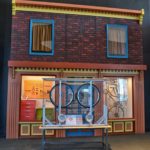
The Drop Tower enables visitors to repeatably drop a racquetball 20 feet onto an angled surface. The angle and material of the surface can be changed, enabling users to experiment with the 2 variables and discover how they affect the trajectory and bounce height of the ball. The targets provide a goal for visitors to aim for, though many simply experiment on their own.

Process

We built and tested several prototypes to determine whether or not our plans were visitor-friendly, the reliability of the ‘dropper’ mechanism, and the feasibility of the chain conveyor.  See images below for more details…

Challenges

  • Reliability was a serious concern since some of the working parts are 20 feet in the air, and difficult to access.
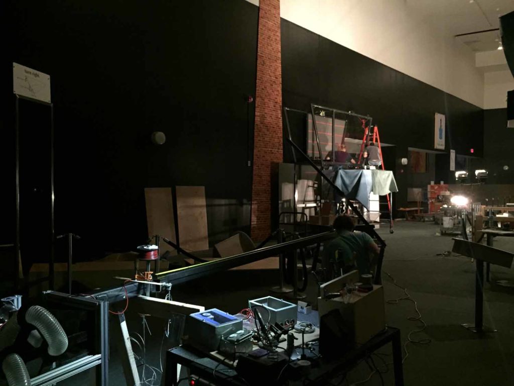
  • The height of the design was difficult since the museum lacks an appropriate lift or convenient ceiling lift points.  The shop ceiling is not much over 8 feet, and the freight elevator is very small, so the components were built in sub-assemblies, test-fit and finished in the shop, and fully assembled on the exhibit floor

Design Details

  • Gear reduction and a rotary damper prevents visitors from spinning the Prism in an uncontrolled fashion
  • Controls for steps 1,2, and 3 (Load, Adjust, Drop) are arranged in sequential order for intuitive operation
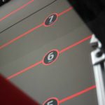
  • An angle indicator makes the experiment replicable
dt2 WEB
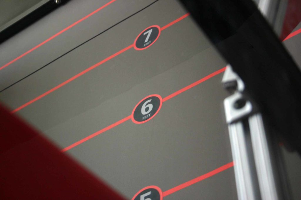
Detail of bounce-height scale
dt5 WEB
Detail of prism rotation indicator
dt3 WEB 2
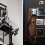
Detail of top module and electrical boxes
Shot Tower Gallery 1
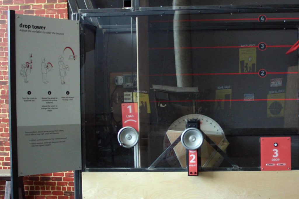
Detail of user controls
DropTowerTesting (2)
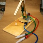
Our first prototype was designed to test some of the mechanical elements, and see how visitors would interact with the component. We found that having 3 different ball types was too much for most visitors, so we eliminated the wiffel ball and golf ball, and kept the racquetball.
DropTowerTesting (4)
Testing to determine the trajectory of dropped balls
DropTowerTesting (1)
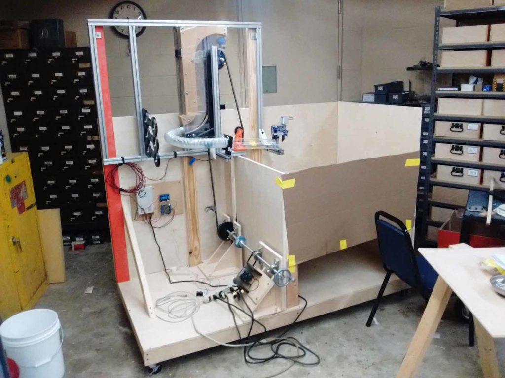
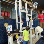
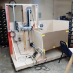
2nd prototype to determine reliability of top module mechanism. The testing revealed some reliability issues that we were able to solve before the Drop Tower was installed.
DropTowerTesting (3)
Testing the 2nd prototype at full height to determine how the chain would act. Thankfully, we found no problems!
DropTower3dModels
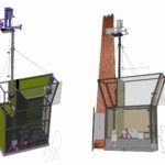
I completed the final Overall design in Rhino at the same time Cole was completing the Top Module design in Solidworks. I then combined our designs and completed final construction drawings in Solidworks.
H-Drop (3)
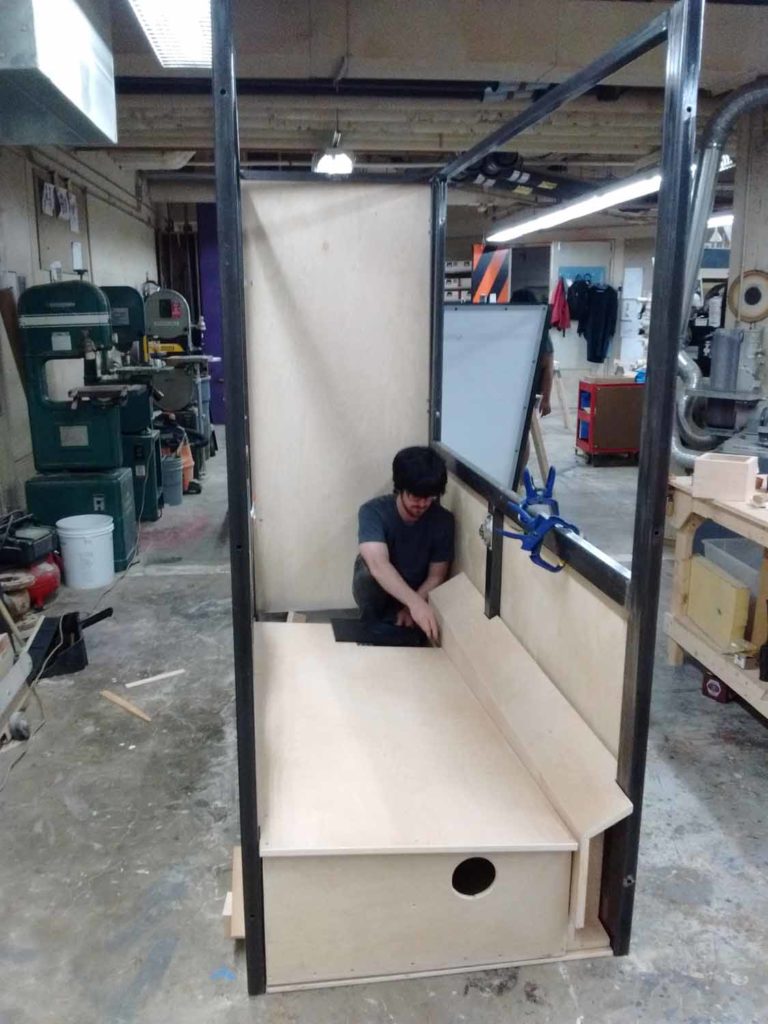
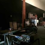
Fabrication in the shop
H-Drop (4)
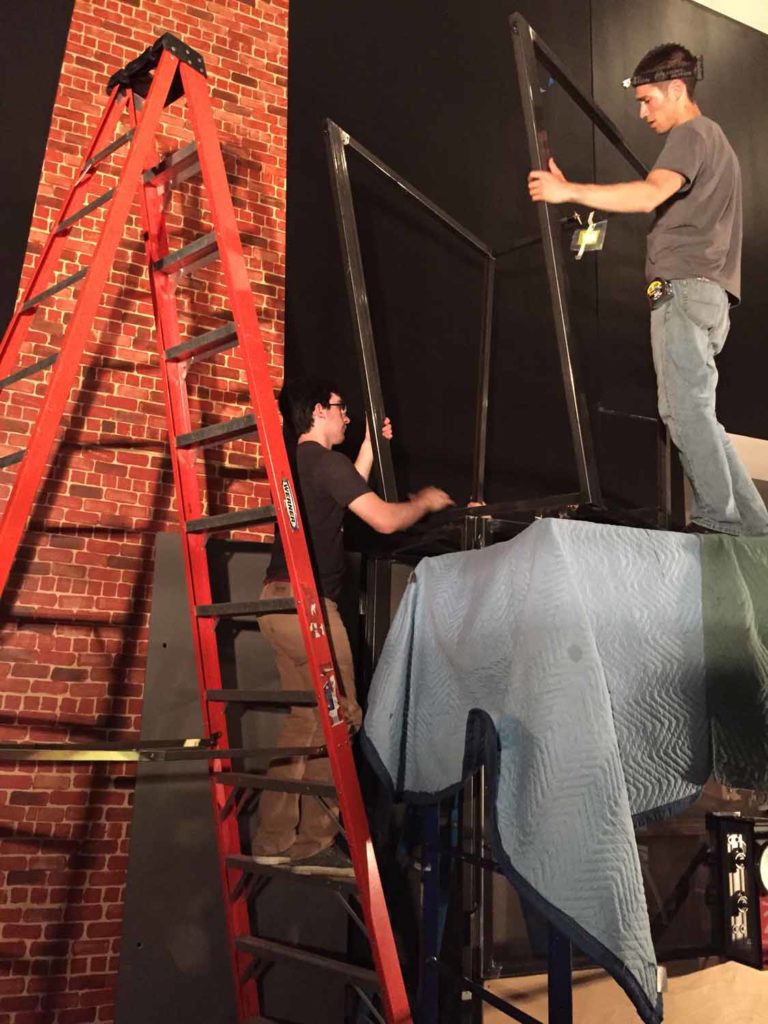
We had to set up during off-hours, since the museum was open 7 days a week
H-Drop (1)
Karl helping with final electrical hookups before final assembly

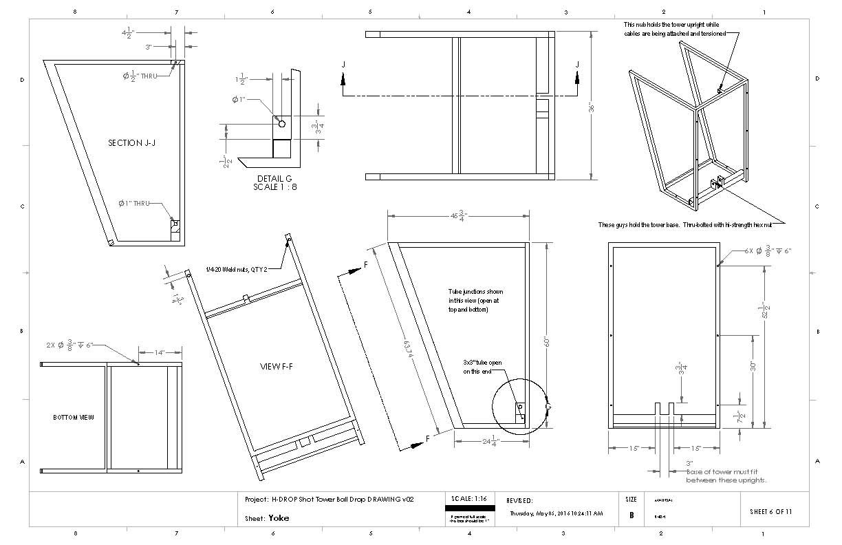
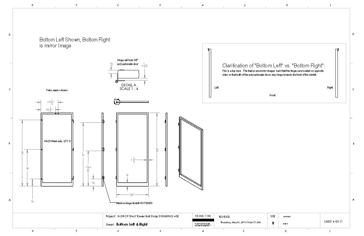
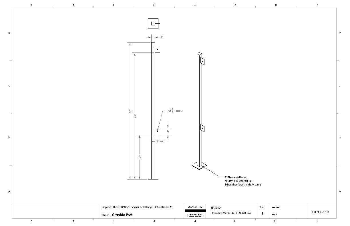
Construction Drawings

Below are examples of construction drawings I created with Solidworks.  They were given to a commercial welding company, who fabricated and delivered the pieces.

Roles

SV: project management, design, fabrication, graphics, electrical, install, break-in, documentation
Cole: ball-dropper mechanism, top-module design, fabrication

Other Contributors

Karl Palm: volunteer advisor for electrical and mechanical engineering
Cole Pritchard: museum employee
Nilam Sari: museum intern
Jacob Nemec: museum intern
Paul Stankiewicz: volunteer

Location

Maryland Science Center, Baltimore MD

Installed

2016

Pipe Organ

Goal

Build a kid-proof pipe organ with exposed inner workings.  As far as I know, this is the only pipe organ in the world that is available for public use.

Design Details

  • Kid-proof keyboard with 1-piece plastic keys
  • ‘Drop the bass’ button for the big zinc pipe
  • All mechanisms visible


Pipes
Detail of the pipes, donated by David Storey
UserAtKeyboard
The moving valves are visible from the player's perspective as she presses the keys
BlowerAndWiring
Detail of regulator, blower, and electronics
KeyboardAndBigButton
Detail of kid-proof keyboard
Pipe organ v03.01 - 30 note_CS4
Illustrator rendering of the design, before I handed design and fabrication responsibilities to Cole.

Roles

Special thanks to David M Storey Inc Pipe Organ Builders for donating parts and providing invaluable advice.

SV: management, technical research, initial designs, electrical
Cole Pritchard: final design, fabrication, tuning, general wizardry

Location

Maryland Science Center, Baltimore MD

Installed

2015

Portable Demo Devices

Goals

  • Build demonstration devices for the MSC Traveling Science Program, which visits schools in Maryland and surrounding states and performs science shows on stage for large audiences.
  • Improve on older designs, which were difficult to set up and take down, and just didn’t work very well
  • Keep items compact for easy transport

Design Details

  • We used simple yet durable materials to make the experiments more relatable, especially since audience members would not be able to touch the experiments.
  • Designed to be maintainable by Education staff, who may not have mechanical experience
p_tspDemo_20
Pendulum snake box. The snake comes off the stands and straight into the box. The box is divided to prevent tangling.
p_tspDemo_05
Pendulum snake string length adjustment jig
p_tspDemo_15
Newton's cradle in action
p_tspDemo_16
Detail of the string adjusters. The nylon washer is easier on the fishing line than metal, and is registered to prevent rotation while the cap screw is tightened.
p_tspDemo_10
Newton's cradle box
p_tspDemo_12
Newton's cradle box
p_tspDemo_04
The stands are designed for quick setup and takedown.
p_tspDemo_09
CO2 gun demo

Roles

SV: management, design, fabrication, documentation
Cole: design and fabrication of CO2 gun demo

Location

Maryland Science Center

Completed

2016

Handy Hydros

Goals

Design and build portable activities that demonstrate hydraulics in action

Design Details

  • Challenge: Facilitators can set up a challenge, such as saving a metal toy dinosaur from a vat of acid, and the user moves the magnet to complete the challenge
  • Durability: I wanted to make the activities out of everyday materials, but it still had to be durable enough to withstand being disassembled and packed for school visits.  The devices didn’t need to be bombproof because a staff facilitator mediated the activity at all times.
  • Service: I used shoulder screws, bushings, and threaded inserts (tee-nuts) to make service as easy as possible.  The syringes are held by a press-fit collar and can be removed without tools.


Handy Hydros (4)
Handy Hydros (2)
Handy Hydros (1)

Roles

SV: Completed all tasks from design to documentation.  Worked with Education staff to ensure their needs were met.

Laugh Garden

Goal

Take a pile of electronics that used to be an exhibit, and give them a second life.

Challenges

The company that originally built the interactive would not return e-mails or calls, so I had to decode configuration files and wade through extraneous hardware to get things working

p_LaughGarden_04
I exposed the electronics in an acrylic-faced cabinet so visitors could get a sense of how the motion-sensing technology worked.
p_LaughGarden_03
p_LaughGarden_02_ps
p_LaughGarden_01
Hardware and software testing in the shop

Roles

SV: project management, computer config, A/V config, design, fab, install, document
Melody Often: mural design and painting (artist website)
Cole Pritchard: assisted with fabrication and install

Spectrum

Goal

Create an exhibit that empowers visitors to explore the science of light and color. See the captions of the images below for more detail:

p_Spectrum_03
Artwork in foreground created by Lansing artist Abbey Hoffman
p_Spectrum_09
p_Spectrum_05
Light Challenge component: I worked with an intern to create the meters, which measured the amount of light concentrated on the photocell. When enough light was concentrated, the meter would turn from red to green.
p_Spectrum_04
The table was designed with an array of small holes so that meters and barriers could be easily moved.
p_Spectrum_02
p_Spectrum_07
Hanging edge-lit graphics, created with the CNC router
p_Spectrum_06
Control panel for the light-painting component
p_Spectrum_08
p_Spectrum_01p
I was responsible for the electronics on the color-mixing activity. We wanted a reliable point-source LED for crisp shadows and zero-maintenance. I sourced and fabricated the LED circuitry and kid-proofed the potentiometers.
Laser SpiroGraph v1.00 DRAWING v02
Final construction drawings, created in Solidworks
Lens Play DRAWING v03
Final construction drawings, created in Solidworks
Lens Play DRAWING v03
Final construction drawings, created in Solidworks

Role

Concept designs, prototyping, electronics, final designs and graphics

Location

Impression 5 Science Center, Lansing MI

Completed

2014

Color-changing Light Mosaic


Goal

The Spectrum exhibit sponsor requested that we include a giant ‘Lite Brite.’  I thought that we could do even better and create a color-changing version, but the complexity and cost of the obvious solution (RGB LEDs and rotary encoders) was prohibitive.  I invented a simple mechanism that consists of 4 parts per peg (2 custom parts, an o-ring, and a dowel pin), and has proven reliable over the years.

Design and Manufacture

Each peg assembly would go through thousands of cycles, and there would be a couple thousand peg assemblies, each with a potential for failure, so I took extra steps to ensure longevity.  See the photos below for more details…

LiteBrite (1)
A Light Mosaic created by artist Abbey Hoffman as a social-media promotion
LiteBrite (5)
p_LiteBrite_ (3)
Visitor creations
p_LiteBrite_ (2)
Visitor creations
LiteBrite (2)
This testing jig was used to test the reliability of a carrier. It simulated an estimated 5 years of use. I made a small change to the design based on this testing.
LiteBrite (3)
I used the in-house ShopBot CNC machine to cut out all custom pieces
LiteBrite (4)
I tracked the parts in batches and coordinated with volunteers to conduct final assembly.
Light Mosaic Drawing v14
Construction drawing of a finished module. The final wall consisted of about 20 100-peg modules.


Roles

I was project lead, handling design through install.  Many volunteers and a few employees assisted with assembly.  My coworker Josh Smith fabricated the cabinet and installed the lighting.

Location

Impression 5 Science Center, Lansing MI

Completed

2014